The network layer as a 'lead' expert
Here we will recognize the two different services provided by the network layer and the core of the network layer, namely the IP protocol. We can understand:
- the concept of virtual interconnection networks.
- the relationship between IP addresses and physical addresses
- the traditional classification of IP addresses (including subnet masks)
Address Resolution Protocol ARP
In practical applications, we often encounter the problem that we already know the IP address of a machine (host or router) and need to find out its corresponding hardware address. The address resolution protocol ARP is used to solve such a problem. Since it is the IP protocol that uses the ARP protocol, it is usually classified as a network layer. However, the purpose of the ARP protocol is to resolve the hardware address used at the data link layer from the IP address used at the network layer.
The following is an overview of the main points of the ARP protocol.
We know that the network layer uses IP addresses, but when transmitting data frames over the links of the actual network, the hardware address of that network must eventually be used. However, there is no simple mapping between IP addresses and the hardware addresses of the network below due to the different formats (for example, IP addresses have 32 bits, while the hardware addresses of a LAN are 48 bits). In addition, new hosts may often be added to a network, or some hosts may be removed. Changing network adapters can also cause the hardware addresses of hosts to change. Address Resolution Protocol ARP solves this problem by storing a mapping table from IP addresses to hardware addresses in the host’s ARP cache, and this mapping table is also dynamically updated (added or deleted on timeout) frequently.
Each host has an ARP cache, which contains the mapping table from IP addresses to hardware addresses of the hosts and routers on the LAN, and these are the addresses that the host knows at present. How does the host know these addresses? We can use the following example to illustrate.
When host A wants to send an IP datagram to a host B on the LAN, it first checks if there is an IP address of host B in its ARP cache. If there is, it will find out the corresponding hardware address in the ARP cache, and then write the hardware address to the MAC frame, and then send the MAC frame to this hardware address through the LAN.
There may also be items where the IP address of host B cannot be checked. This may be because Host B has only just entered the network, or it may be that Host A has just been powered up and its cache is still empty. In this case, Host A runs ARP automatically and then follows the steps below to find out the hardware address of Host B.
The ARP process broadcasts and sends an ARP request packet on the local area network. An example of the main content of the ARP request packet is: “My IP address is 209.0.0.5 and my hardware address is 00-00-C0-15-AD-18. I want to know the hardware address of the host with IP address 209.0.0.6.”
This ARP request packet is received by all ARP processes running on all hosts on this LAN.
The IP address of host B matches the IP address to be queried in the ARP request packet, so it receives this ARP request packet and sends an ARP response packet to host A, and writes its own hardware address in this ARP response packet. Since the IP addresses of all the other hosts do not match the IP address in the ARP request packet, they ignore the ARP request packet. The main content of the ARP response packet is: “My IP address is 209.0.0.6, and my hardware address is 08-00-2B-00-EE-0A.” Note that although the ARP request packet is sent broadcast, the ARP response packet is plain unicast, i.e., it is sent from a source address to a destination address.
Once host A receives the ARP response packet from host B, it writes the mapping from host B’s IP address to the hardware address in its ARP cache.
When host A sends a datagram to B, it is likely that host B will have to send another datagram to A shortly thereafter, and thus host B may also have to send an ARP request packet to A. To reduce the amount of traffic on the network, host A writes its IP address to the hardware address mapping into the ARP request packet when it sends its ARP request packet. When host B receives A’s ARP request packet, it writes this address mapping of host A into host B’s own ARP cache. It is convenient for host B to send datagrams to A later.
As you can see, the ARP cache is very useful. If the ARP cache is not used, then any host that communicates once must send the ARP request packet over the network by broadcast, which greatly increases the amount of communication over the network. The next time a host communicates with a host with the same destination address, it can find the required hardware address directly from the cache instead of sending the ARP request packet by broadcast.
ARP sets a survival time (e.g., 10 to 20 minutes) for each mapped address item stored in the cache. Any item that exceeds the survival time is removed from the cache. It is important to set the survival time of such address mapping items. Imagine a situation where hosts A and B communicate. Host A communicates with B. A’s ARP cache has B’s hardware address stored in it. But B’s network adapter suddenly breaks down and B immediately replaces it with a new one, so B’s hardware address changes. Assuming that A wants to continue communicating with B, A finds B’s original hardware address in its ARP cache and sends data frames to B using that hardware address. However, B’s original hardware address is no longer valid, so A cannot find host B. But after a short period of time, A’s ARP cache has deleted B’s original hardware address, so A rebroadcasts the ARP request packet and finds B again.
Note that ARP is a solution to the problem of mapping IP addresses and hardware addresses of hosts or routers on the same LAN. The resolution from IP addresses to hardware addresses is automatic, and the user of the host is not aware of this address resolution process. Whenever a host or router wants to communicate with another host or router on this network with a known IP address, the ARP protocol automatically resolves that IP address to the hardware address required at the link layer.
ARP
IPv4
The format of an IP datagram can illustrate what functions the IP protocol has. An IP datagram consists of two parts: the header and the data. The first part of the header is a fixed length of 20 bytes, which is mandatory for all IP datagrams. Following the fixed part of the header are optional fields that are variable in length. The following describes the meaning of each field in the header.
-
Version Occupies 4 bits and refers to the version of the IP protocol. The version of the IP protocol used by both communicating parties must be the same. The current widely used IP protocol version number is 4 (i.e. IPv4).
-
Header Length The maximum decimal value that can be represented is 15. Please note that the unit of the number represented by the initial length field is a 32-bit word (one 32-bit word is 4 bytes long). Since the fixed length of the IP prefix is 20 bytes, the minimum value of the prefix length field is 5 (i.e., the binary representation of the prefix length is 0101). And when the prefix length is the maximum value 1111 (i.e., 15 in decimal), it indicates that the prefix length reaches a maximum of 15 32-bit words long, i.e., 60 bytes. When the IP packet’s initial length is not an integer multiple of 4 bytes, it must be padded using the final padding field. Therefore, the data portion of an IP datagram always starts at an integer multiple of 4 bytes, which is more convenient when implementing IP protocols. The disadvantage of limiting the initial length to 60 bytes is that sometimes it may not be enough. However, this is done in the hope that the user will minimize the overhead. The most common prefix length is 20 bytes (i.e., a prefix length of 0101), at which point no options are used.
-
Differentiated Services It takes up 8 bits and is used to get better service. This field was called Service Type in the old standard , but it was never actually used.
-
Total Length The total length is the length of the sum of the header and data in bytes. The total length field is 16 bits, so the maximum length of a datagram is 2 16 - 1 = 65535 bytes. However, in practice, it is very rare to transmit such a long datagram.
Flow of IP layer forwarding packets
We know that there is a routing table in the router, but if the routing table points to each host how to forward, that would make the routing table too large, but if the routing table only points to a network how to forward, then the routing table will only include the number of network items, which greatly reduces the need to store items, we do not have to care about the specific topology of a network and the specific number of devices connected to the network, because from one router to the next router forwarding.
The most important items in the routing table are the following two pieces of information: $$ (Destination network address, next-hop address) $$
ICMP(Internet Control Message Protocol)
In order to forward IP datagrams more efficiently and to improve the chances of successful delivery, the ICMP protocol is used at the network layer. The ICMP protocol allows hosts or routers to report errors and provide reports on exceptions. It is important to note that ICMP is not a high-level protocol, but rather remains a network layer protocol, as ICMP messages are packed into IP datagrams as part of the data.
“TOS” and “Protocol” are related to ICMP in the introduction to the packet header structure.
The description given in the professor’s slide is also great:
Das Internet Control Message Protocol (ICMP) dient dazu, • in derartigen Fällen den Absender über das Problem zu benachrichtigen und • stellt zusätzlich Möglichkeiten bereit, um z. B. • die Erreichbarkeit von Hosts zu prüfen („Ping“) oder • Pakete umzuleiten (Redirect).
Types of ICMP messages
IPv6
IPv6 Basic Header
After IPv4 ran out of addresses, we naturally needed to expand the IP address block, hence IPv6. IPv6 still supports connectionless transport, but refers to the protocol data unit PDUs as packets, rather than IPv4 datagrams.
The main changes in IPv6 are as follows:
- Larger address space, increasing the 32-bit IPv4 address space to four times that of IPv4, i.e., to 128 bits.
- Extended address hierarchy.
- Flexible prefix format.
- Improved options. 5.
- Allows protocols to continue to expand. 6.
- IPv6 prefixes are now 8-byte aligned (i.e., the prefix length must be an integer multiple of 8 bytes), whereas IPv4 prefixes were 4-byte aligned.
Compared to IPv4, IPv6 has changed some fields in the header as follows:
- The length field of the header has been removed, since the length of the header is fixed (40 bytes)
- The Type of Service (TOS) field has been removed, since the Priority and Flow Label Number fields implement the function of the Type of Service field
- The total field length has been removed in favor of the payload length field
- Eliminated the Identification, Flag and Slice Offset fields, but the role is the same
- The protocol field has been removed
- Check sum field has been removed
- Removed optional fields
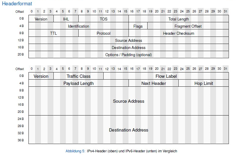
IPv4-Header (oben) und IPv6-Header (unten) im Vergleich
IPv6 Basic Prefix Segments Role
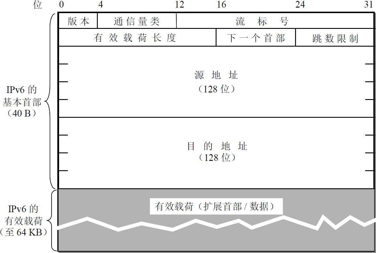
IPv6 Header
-
version 4 bits, specifies the protocol version, for IPv6 this field is 6
-
traffic class 8 bits. This is to distinguish the class or priority of different IPv6 datagrams. We are currently experimenting with different traffic performance.
-
flow label 20 bits. A new mechanism in IPv6 is to support resource preallocation and allow routers to associate each datagram with a given resource allocation. IPv6 introduces the abstract concept of flow. A “flow” is a series of datagrams () on an interconnected network from a specific source to a specific destination (unicast or multicast), and the routers in the path of this “flow” are guaranteed the specified quality of service. All datagrams belonging to the same stream have the same stream label. Therefore, stream tagging is particularly useful for real-time audio/video data delivery. 4.
-
payload length is 16 bits. It specifies the number of bytes in the IPv6 datagram in addition to the base header (all extended headers are counted as part of the payload). The maximum value of this field is 64KB (65535 bytes)
-
next header 8 bits. It is equivalent to the optional field of the IPv4 protocol field.
-
hop limit 8 bits. Used to prevent datagrams.
-
Source address 128 bits. It is the address of the sender side of the datagram. 8.
-
Destination address 128 bits. It is the IP address of the receiving end of the datagram.
Let’s introduce the extended initials of IPv6.
As you know, if an IPv4 datagram uses options in its header, each router along the path of the datagram must check each of these options, which slows down the processing of the datagram by the router. IPv6 puts the functionality of the options in the original IPv4 header in the extended header, and leaves the extended header to the hosts at the source and destination at each end of the path, while none of the routers** through which the datagram passes process the extended header** (with the exception of one header). (with the exception of one, the hop-by-hop option for extended headers), which ** greatly improves the processing efficiency of the router **.
We will probably encounter these six extended headers: (1) hop-by-hop option; (2) routing; (3) fragmentation; (4) identification; (5) encapsulation security payload; and (6) destination option.
Each extension header consists of a number of fields, and they vary in length. However, the first field of all extension headers is the 8-bit “next header” field. The value of this field indicates what field follows the extension header. When multiple extension headers are used, they should appear in the above order. High-level headers are always placed last.
IPv6 Addresses
n general, the destination address of an IPv6 datagram can be one of the following three basic types of addresses:
- unicast Unicast is peer-to-peer communication
- multicast
- anycast
IPv6 refers to both hosts and routers that implement IPv6 as nodes. Since a node may use multiple links to connect to some other nodes, a node may have multiple interfaces to the links. Thus, IPv6 assigns an IP address to each interface of a node. A node can have multiple unicast addresses, and any one of them can be used as the destination address to reach the node.
ICMPv6
Like IPv4, IPv6 does not guarantee reliable delivery of datagrams, as routers in the Internet may drop them. Therefore, IPv6 also needs to use ICMP to feed back some error messages. The new version is IPv6, which is much more complex than ICMPv4. The functions of the address resolution protocols ARP and IGMP have been merged into ICMPv6.
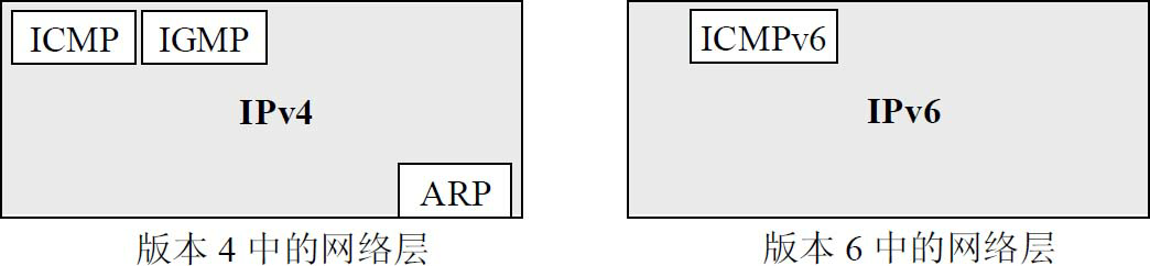
Comparison of the network layer in the old and new versions
ICMPv6 is a message-oriented protocol that uses messages to report errors, obtain information, probe neighboring stations, or manage multicast traffic. ICMPv6 adds several other protocols that define the function and meaning of messages. Different literature and RFC documents use different strategies when categorizing ICMPv6 messages, some defining some of them as ICMPv6 messages and others as Neighbor-Discovery ND (Neighbor Discovery) messages, using the NDP protocol (Neighbor Discovery Protocol) or multicast Protocol)** or Multicast Listener Delivery (MLD) messages. In fact, all these messages should be ICMPv6 messages, just with different functions and roles. Therefore, we include all these messages in different categories of ICMPv6. The reason for using this classification is that all these messages have the same format and all message types are handled by the ICMPv6 protocol.
Structure of ICMPv6 messages:
ICMPv6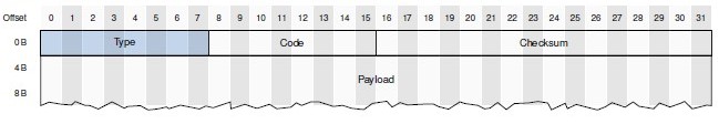
Routing
Longest Prefix Matching
When using CIDR, since this notation of network prefix is used, the IP address consists of two parts: network prefix and host number, so the items in the routing table have to be changed accordingly. At this time, each item consists of “network prefix” and “next-hop address”. But when looking up the routing table you may get more than one match . This raises the question: which route should we choose from these matches?
The correct answer is: the route with the longest network prefix should be selected from the match results. This is called longest-prefix matching, because the longer the network prefix, the smaller the address block, and therefore the more specific the route. Longest-prefix matching is also known as longest matching or best matching.
Die Routingtabelle wird von längeren Präfixen (spezifischeren Routen) hin zu kürzeren Präfixen (weniger spezifische Routen) durchsucht. Der erste passende Eintrag liefert das Gateway (Next-Hop) eines Pakets. Diesen Prozess bezeichnet man als Longest Prefix Matching.